Features
◆ This 1550nm optical transmitter can be used in long-distance transmission.
◆ Double microwave source SBS control, +13~+19dBm adjustable, 0.5dB step.
◆ Adopt the DFB laser and LiNbO3 external modulator.
◆ Support Ethernet transponder
◆ Support WEB and SNMP network management.
◆ Hot backup dual power modules
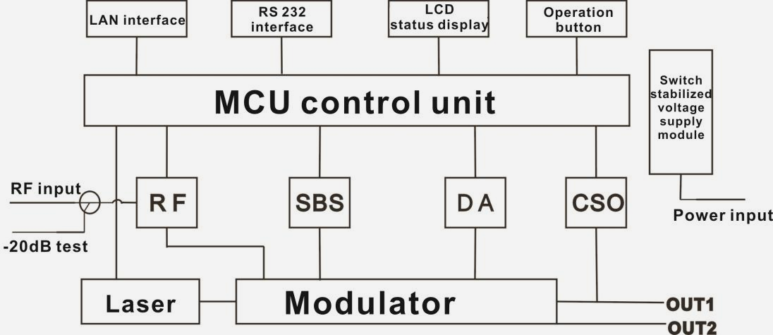
Block Diagram
Technical Parameters
Optical Parameters
| Item |
Unit |
Value |
| Optical Wavelength |
nm |
1545~1560 (or specified by the user) |
| Side-mode Suppression ratio |
dB |
>30 |
| Relative Intensity Noise |
dB/Hz |
<-160 |
| Wavelength Adjustment Range |
GHz |
+/-50GHz |
| Optical Power |
dBm |
2x5, 2x6, 2x7, 2x8, 2x9, 2x10 |
| SBS Threshold Value |
dBm |
+13~+19 (Continuously adjustable) |
| Laser Linewidth |
MHz |
0.3 |
Model Test Indicators
| Test Model |
C42 |
D59 |
D84 |
| Channel Plan |
CENELEC42 |
PAL D59 |
PAL D84 |
| Channel Number TV/FM/QAM64 |
42/0/0 |
59/0/0 |
84/0/0 |
| Bandwidth Noise |
5 |
5 |
5 |
| CNR Tx/Rx |
55 |
54 |
52.5 |
| CNR Link 1 |
54 |
53.5 |
52 |
| CNR Link 2 |
53 |
52.5 |
50.5 |
| CNR Link 3 |
50.5 |
50.5 |
49 |
| CSO Tx/Rx and Link 1 |
64 |
64 |
64 |
| CSO Link 2 |
63 |
64 |
64 |
| CSO Link 3 |
62 |
62 |
62 |
| CTB |
62 |
62 |
62 |
Test Condition
|
First stage EDFA |
First paragraph fiber length |
Second stage EDFA |
Second paragraph fiber length |
RX |
SBS |
| (dBm) |
| Tx/Rx |
No |
No |
No |
no |
0dBm |
13.5 |
| Link 1 |
No |
35km |
no |
no |
0dBm |
13.5 |
| Link 2 |
16dBm |
65km |
no |
no |
0dBm |
16 |
| Link 3 |
13dBm |
50km |
13dBm |
50km |
0dBm |
13.5 |
Technical Data Sheet
| Item |
Unit |
Technical Parameters |
| RF range |
MHz |
47~1003 |
| RF flatness |
dB |
±0.75 |
| RF return loss |
dB |
>16 |
| RF input impedance |
Ω |
75 |
| RF input connector type |
|
F type |
| Input level range |
dBµV |
80±5 |
| AGC control range |
dB |
+3~-3 |
| MGC adjustable range |
dB |
0~15 |
| Optical connector |
|
SC/APC, FC/APC |
| Operating temperature |
°C |
-5~45 |
| Storage temperature |
°C |
-30~+70 |
| Power Source Specification |
V |
90~265VAC |
| 36~72VDC |
| Consumption |
W |
≤60 |
| Dimension |
mm |
483(L) × 455(W) × 44(H) |
| Total Weight |
kg |
5.5 |
External Function Description:
Front Panel
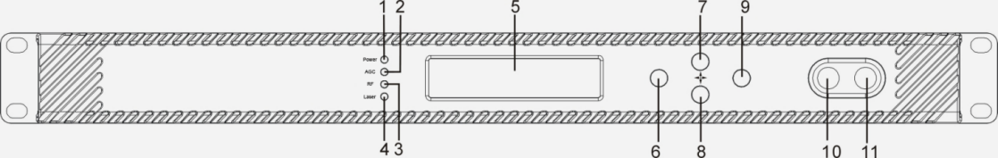
| 1 |
Power indicator |
2 |
AGC indicator |
3 |
RF indicator |
| 4 |
Laser indicator |
5 |
LCD |
6 |
ESC key |
| 7 |
UP key |
8 |
DOWN key |
9 |
Enter key |
| 10 |
RF input port (optional) |
11 |
-20dB RF input test port |
|
|
Indicator Description
| Power indicator |
One power supply |
LED yellow |
| Two power supplies |
LED green |
| AGC indicator |
AGC mode |
LED green |
| MGC mode |
LED off |
| RF indicator |
Normal |
LED green |
| Abnormal |
LED flash red |
| Laser indicator |
Bias current, cooling current and output power are all normal |
LED green |
|
At least one of bias current, cooling current and output power is abnormal |
LED flash red |
Rear Panel
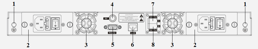
| 1 |
Ground stud |
2 |
Power module |
3 |
Fan |
| 4 |
RF input port (or on the front panel, optional) |
5 |
RS232 interface |
6 |
LAN interface |
| 7 |
Optical output interface A (or on the front panel, optional) |
8 |
Optical output interface B (or on the front panel, optional) |
|
|
Power Module
220V Power Module

| 1 |
Mounting screws |
| 2 |
220V power outlet |
| 3 |
Fuse |
| 4 |
Power switch |
48V Power Module
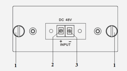
| 1 |
Mounting screws |
| 2 |
+ Positive terminal block |
| 3 |
- Negative terminal block |
Menu System
Main Menu
| Display |
Comments |
| 1.Disp Parameters |
Menu one: Display parameters |
| 2.Set Parameters |
Menu two: Set parameters |
| 3.Alarm Status |
Menu three: Alarm status |
Display Menu
| Display |
Comments |
Display |
Comments |
| Laser Output |
Output optical power |
+24V Read: |
+24V monitor voltage |
| Laser Bias |
Laser current |
+12V Read: |
+12V monitor voltage |
| RF CSO |
CSO monitor voltage |
-12V Read: |
-12V monitor voltage |
| Laser Cooling |
Cooling current |
LASER: |
Laser status |
| OMI(rms) |
Total modulation degree |
SBS Module Temp: |
SBS module temperature |
| RF Mode |
RF control mode |
BOX Temp: |
Overall temperature |
| AGC |
Adjusted value with AGC mode |
MCU Temp: |
MCU temperature |
| MGC |
Adjusted value with MGC mode |
S/N: |
Serial number |
| +5V Read: |
+5V monitor voltage |
Version: |
Version number |
| -5V Read: |
-5V monitor voltage |
Work Time: |
Work time |
Set Menu
| Display |
Comments |
Remarks |
| Set RF MODE |
Set RF control mode |
MGC and AGC two modes selectable |
| Set AGC |
Set MGC |
Set RF adjusted value |
Adjustable range 0~15dB with MGC mode |
| Adjustable range -3~+3dB with AGC mode |
| Set SBS Suppression |
Set SBS value |
Range 13~19dBm, 0.5dB stepping |
| Set ITU |
Set optical wavelength |
Range ±50GHz |
| Set Channel Distance |
Set channel distance |
6MHz, 7MHz, 8MHz |
| Set LASER |
Set laser status |
ON/OFF |
| Set IP Address |
Set IP address |
|
| Set Mask |
Set subnet mask |
|
| Set Gateway |
Set gateway |
|
| Set Trap1 Address |
Set trap1 address |
|
| Set Trap2 Address |
Set trap2 address |
|
| Set Buzzer Alarm |
Set buzzer alarm |
ON/OFF |
| Restore Factory Cfg |
Restore factory settings |
|
Alarm Menu
| The displayed alarm content |
Comment |
| RF IN Status |
HIGH(LOW) |
The RF input signal is high (low) |
| Laser Bais |
HIGH(LOW) |
The laser bias current is high (low) |
| Laser TEC |
HIGH |
The laser cooling current is high |
| OutPutPower Status |
HIGH(LOW) |
The output optical power is high (low) |
| -5V Status |
HIGH(LOW) |
The -5V voltage is high (low) |
| +5V Status |
HIGH(LOW) |
The +5V voltage is high (low) |
| +12V Status |
HIGH(LOW) |
The +12V voltage is high (low) |
| -12V Status |
HIGH(LOW) |
The -12V voltage is high (low) |
| +24V Status |
HIGH(LOW) |
The +24V voltage is high (low) |
| Laser |
OFF |
The laser is off |
| CSO Initialization failed |
|
The CSO initialization is failed |
| Power invalid |
LEFT(RIGHT ) |
The left (right) power is invalid |
Communication Setup Descriptions:
Communication Interface Description
1) RS232 communication interface adopts DB9 standard connector, the pin definitions as follow:
The serial communication uses the standard NRZ form, 1 starts bit, 8 data bits, 1 stop bit and the baud rate is 38400.
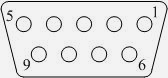 |
1:No Connect |
2:TX |
3:RX |
| 4:No Connect |
5:GND |
6:No Connect |
| 7:No Connect |
8:No Connect |
9:No Connect |
2) LAN communication interface adopts RJ45 standard connector, the pin definitions as follow:
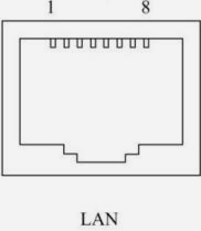 |
1:TX+ |
2:TX- |
3:RX+ |
| 4:No Connect |
5:No Connect |
6:RX- |
| 7:No Connect |
8:No Connect |
|
WEB Network Management
1. Open the IE browser, type the IP address and enter the interface as follows:
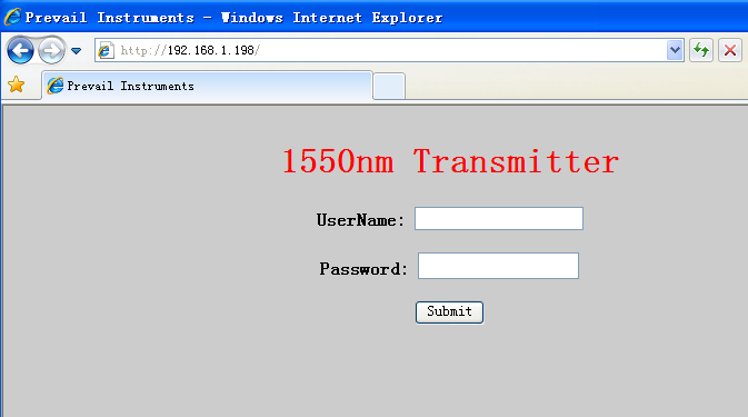
2. Type the user name admin and the password 123456 (factory default), enter the following interface:
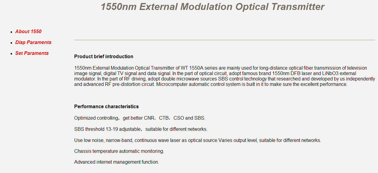
There are 3 sub-interfaces:
1) About1550 interface: Mainly described the basic information of the equipment.
2) Disp Paraments interface: Mainly described the display menu of the equipment.
3) Set Paraments interface: Change the device parameters in this interface.
2. Click Set Paraments to enter Set Paraments interface as follows:

The Item and Items columns list the parameters that can be changed, the Current column lists the present parameter values, the New column can select or type the new parameter values, and the Update column can update the parameters.
The steps to change the parameters: find the item in the Item column, select the new parameter values in the New column, and click the corresponding Update button to update the parameters.
The change steps in the Items are the same, but finally need to click the Restart Device button to take effect.
Attention
● Before powering on, make sure that the grounding terminals of the chassis and power socket are reliably grounded, and the grounding resistance should be <4Ω, which can effectively protect against surges and static electricity.
● Optical transmitter is a highly technical professional equipment,its installation and debugging must be operated by professional technicians. Read this manual carefully before operating to avoid damage to equipment caused by fault operation or accident harm to the operator.
● When installing and debugging optical equipment, invisible laser beams may be emitted inside the fiber connector.Avoiding permanent harm to the body and eye, the fiber connector should not aim at the human body and human should not look directly at the fiber connector with the naked eye!
● There must be no shielding outside the ventilation holes of the device. Poor ventilation will cause the index to decrease, and in serious cases will cause damage to the device.
● When cleaning the fiber end face, you must confirm that the optical source is turned off.
● When the fiber connector is not in use, put a dust cover to avoid dust pollution and keep the end surface of the optical fiber clean.
● When installing the fiber connector, apply appropriate force to avoid damage to the adapter. Otherwise, the output optical power may decrease.
Installation
● Installation must be operated by professional technicians.
● Mounting the equipment in the standard 19 inch equipment rack.The fixing screws must be tightened after the equipment is installed in place.
● Reliably ground the equipment. The ground terminal is on the rear panel.Visually inspect each key (button) on the front panel to ensure that each button can move freely.
● Screw on the matched RF cable.
● Correctly clean the optical connector and connect the optical fiber.
● Connect an Ethernet cable.
● After all the steps are completed, make sure that the machine is intact and powered on.