Performance Characteristics
● 1.2GHZ band, support DOCSIS 3.1 system.
● The AGC and MGC gain control modes are optional.
● Two inputs with 50dB isolation for high quality RF insertion.
● Dual power supply; hot backup; a variety of power supply options are available, optional AC100-240V and DC48V.
● Laser output power, bias current and cooling current are detected in real time.
● Optional CWDM for optical signal insertion.
● Electronically controlled dispersion compensation can support a transmission distance of 50KM.
● Low-cost solution is comparable to the performance of external modulated transmitter.
● ITU standard wavelength is optional.
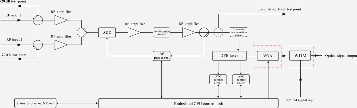
Block Diagram
Technique Parameters
| Item |
Unit |
Parameter |
| Optical part |
| Optical wavelength |
nm |
ITU wavelength |
| Laser type |
|
Butterfly-typed DFB laser |
| Optical modulation mode |
|
Direct optical intensity modulation |
| Optical connector type |
|
FC/APC or SC/APC |
| Output optical power |
mW |
4~10 |
The insertion loss of the VOA and CWDM(+6dBm ~ +10dBm) is excluded. |
| External optical signal input |
dBm |
-5~10 |
| RF part |
| Frequency range |
MHz |
47~870/1003/1218 |
| RF input level |
dBuV |
77± 5 |
| Flatness in band |
dB |
± 0.75 |
| Input return loss |
dB |
≥ 16 |
| RF AGC control range |
dB |
±5 |
| RF MGC adjustable range |
dB |
0~20 |
| RF input isolation |
dB |
≥ 50 |
Isolation between two RF inputs |
| RF input test port |
dB |
-20±1 |
| Laser drive level test port |
dB |
-20±1 |
| Electronically controlled optical attenuator tolerance |
dB |
≤1: ATT 0-15dB |
|
|
≤3: ATT 16-20dB |
| CNR |
dB |
≥ 48 |
550MHZ 59CH analog signal 77dBuV/CH
550-870MHZ 40CH digital signal 67dBuV/CH
25 Km, -1dBm input |
|
|
|
|
| C/CSO |
dB |
≥ 58 |
| C/CTB |
dB |
≥ 63 |
| CNR |
dB |
≥ 46 |
550MHZ 59CH analog signal 77dBuV/CH
550-870MHZ 40CH digital signal 67dBuV/CH
50Km, -1dBm input |
|
|
|
|
| C/CSO |
dB |
≥ 55 |
| C/CTB |
dB |
≥ 63 |
| MER |
dB |
≥ 40 |
25 Km, -1dBm input, 96CH digital 77dBuV/CH |
| ≥ 39 |
50 Km, -1dBm input, 96CH digital 77dBuV/CH |
| Others |
| Maximum power consumption |
W |
≤10 |
| Operating temperature |
℃ |
-5 ~ + 55 |
| Storage temperature |
℃ |
-30 ~ + 70 |
| Weight |
Kg |
5.5 |
Operation instructions of the display menu
▲▼ key: The cursor can be moved left or right or up and down, and the selected module or menu is highlighted.
Enter key: Press Enter to enter the next submenu or set the parameters in the submenu. Press Enter to confirm.
ESC key: Exit or return to the previous menu.
The menu displayed after power on: Press Enter to enter the first level submenu:

| 1. Disp Parameters |
Parameter display menu
|
| 2. Set Parameters |
Parameter setting menu
|
| 3. Alarm Status |
Alarm status
|
Disp Parameters, the second level submenu:
| Laser Output |
xx dBm |
Laser output optical power
|
| Voa Input |
xx dBm |
Optical power after attenuation (without WDM, no this menu)
|
| Master Input |
xx dBm |
External optical signal power (without WDM, no this menu)
|
| Laser Bias |
xx mA |
Laser bias current
|
| Laser Temp |
xx ℃ |
Internal temperature of the laser
|
| Tec current |
xx A |
Laser cooling current
|
| RF Chan No |
xx |
Transmission channel numbers
|
| Laser RF |
xx dBuV |
Laser drive level
|
| RF Ctrl Mode |
AGC |
RF control mode
|
| AGC Ref |
x dB |
AGC offset (in AGC mode)
|
| MGC ATT |
x dB |
MGC attenuation (in MGC mode)
|
| Wave Length |
1550 |
+5V monitoring voltage
|
| +5V Read |
x v |
-5V monitoring voltage
|
| -5V Read |
x v |
+24V monitoring voltage
|
| +24V Read |
x v |
Equipment wavelength
|
| S/N |
|
Serial number
|
| BOX Temp |
xx ℃ |
Current internal temperature
|
| IP Address |
|
Equipment IP address
|
| Mask |
|
Equipment subnet mask
|
| GTW |
|
Equipment gateway
|
| Mac |
|
Equipment MAC address
|
| SoftWare Ver |
|
Equipment software version number
|
Set Parameters, the second level submenu:
| SetLaserOutputUnit |
dBm |
Optical power unit: dBm, mW optional
|
|
| Set BuzzerAlarm |
ON |
Buzzer alarm: ON, OFF optional
|
|
| SetRF ControlMode |
AGC |
RF control mode: AGC, MGC optional
|
|
| Set MGC ATT |
XX dB |
MGC attenuation: 0-20 optional
|
|
| Set AGC Ref |
XX dB |
AGC offset: ±3dB optional
|
|
| Set OPT ATT Mode |
AUTO |
Set the optical power attenuation mode: AUTO or Manu optional
|
Without WDM, no this menu
|
| Set OPT ATT |
XX dB |
Set the optical power attenuation value: 0~15dB optional
|
| Set OPT Delta |
XX dB |
Set the difference between the main optical power and the inserted optical
|
| Set FiberC Length |
xxKM |
Set transmission distance: 0~50KM optional, 1KM stepping.
|
|
| SetChannel Number |
XX |
Set the channel number: 0-100 optional
|
|
| Set IP Addr |
|
Set the equipment IP address
|
|
| Set Subnet Mask |
|
Set the subnet mask
|
|
| Set GateWay |
|
Set the gateway
|
|
| Restore Factory Config |
|
Reset to the default
|
|
Alarm Status, the second level submenu:
| Laser RF |
Laser level alarm: The default normal range is 80~110dBuV, which can be set through the network
|
| Laser Temp |
Laser temperature alarm: The default normal range is 25±10°C, which can be set through the network
|
| Laser Bias |
Laser bias current alarm: The default normal range is 20~90mA, which can be set through the network
|
| Laser TEC |
Laser cooling current: The default normal range is -1.5~1.5A, which can be set through the network
|
| Laser Output |
Output optical power alarm: The default normal range is 2 to 25 mW, which can be set through the network
|
| +5V Alarm |
+5V alarm: The default normal range is 5±1V, which can be set through the network management.
|
| -5V Alarm |
-5V alarm: The default normal range is -5±1V, which can be set through the network management.
|
| +24V Alarm |
+24V alarm: The default normal range is 24±2V, which can be set through the network management.
|
Structure Description
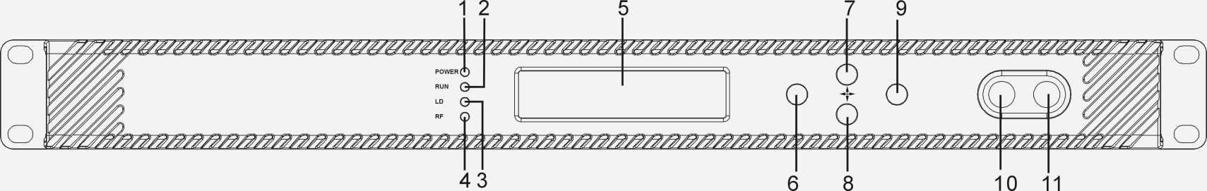
Front panel
| 1 |
Power indicator |
| 2 |
Device running indicator: This indicator will flash by 1Hz frequency after the device start running normally. |
| 3 |
Laser working status indicator: |
|
| Steady green light: The laser is operating normally. |
|
| Steady red light: The laser is not turned on. |
|
| Blinking red light: The device has a parameter alarm. You can view the alarm in the Alarm Status, the second level submenu. |
| 4 |
Laser drive level indicator: |
|
| Steady green light: Drive level is normal. |
|
| Blinking red light: Drive level alarm. You can view the alarm in the Alarm Status, the second level submenu. |
| 5 |
160×32 dot-matrix LCD screen: used to display all the parameters of the machine. |
| 6 |
Display the exit or cancel key of the setup menu. |
| 7 |
Display the up or increase key of the setup menu. |
| 8 |
Display the down or decrease key of the setup menu. |
| 9 |
Display the enter key of the setup menu. |
| 10 |
Laser switch: |
|
| ON: The laser is on. |
|
| OFF: The laser is off. |
|
| Keep the laser off before the device is powered on, and turn on the laser after the self-inspection is completed when power on. |
| 11 |
Laser drive level test port: -20dB |
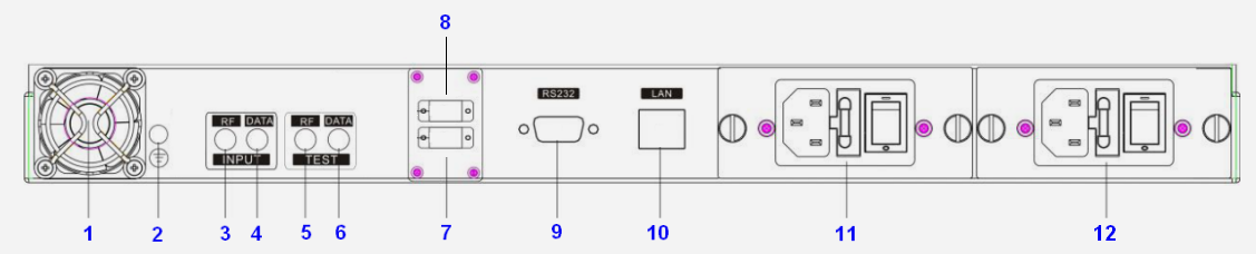
Rear panel
| 1 |
Fan |
7 |
Optical signal output |
| 2 |
Ground stud, ensure good grounding before power on |
8 |
Optical signal input: without WDM, no this port |
| 3 |
RF input 1 |
9 |
RS232 interface |
| 4 |
RF input 2 |
10 |
LAN interface |
| 5 |
RF input 1 test port -20dB |
11 |
Power module 1, hot swappable |
| 6 |
RF input 2 test port -20dB |
12 |
Power module 2, hot swappable |
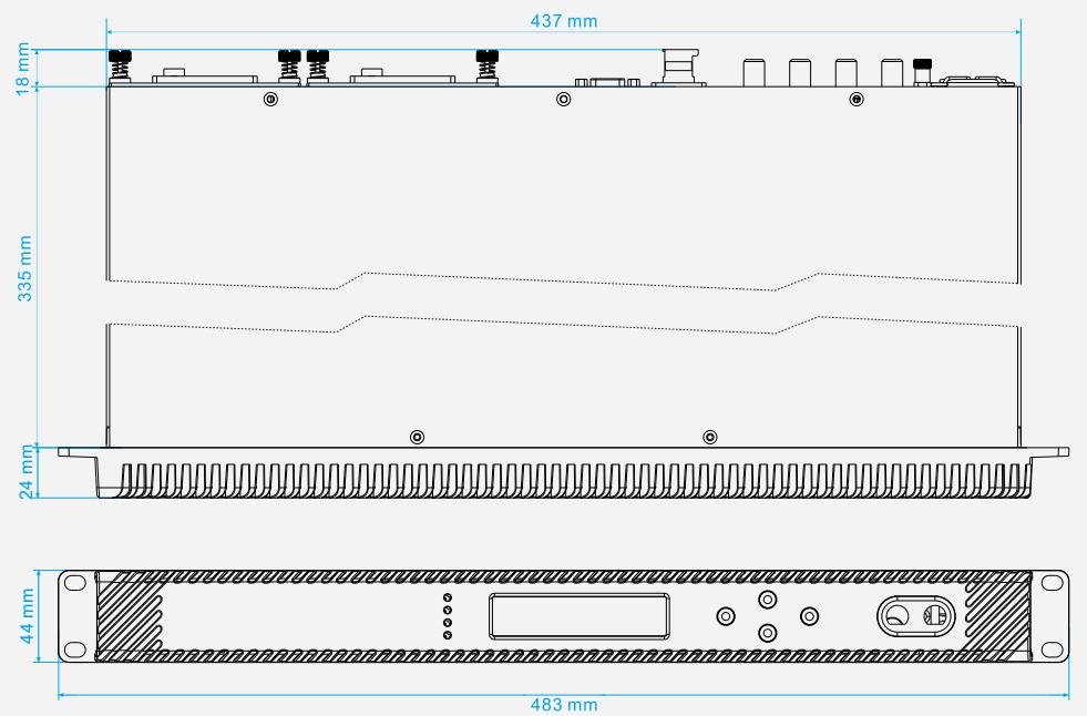
Dimension
Attention
● Insure the package is not defaced. If you think the equipment has been damaged, please don't electrify to avoid worse damage or do harm to the operator.
● Before the equipment is power on, make sure the housing and the power socket is reliably grounded. The grounding resistance should be <4Ω, so as to effectively protect against surges and static electricity.
● Optical transmitter is professional equipment. Its installation and debugging must be operated by special technician. Read this manual carefully before operating to avoid damage to equipment caused by fault operation or accident harm to the operator.
● While the optical transmitter is working or debugged, there is an invisible laser beam from the optical output adapter on the front panel. Avoiding permanent harm to the body and eye, the optical output should not aim at the human body and people should not look directly at the optical output with the naked eye!
● When the fiber connector is not in use, it should be put on the dust jacket to avoid dust pollution and keep the fiber tip clean.